How to Plan a Grow Room Layout: Space, Airflow, and Access
Plan an indoor grow room around fixed dimensions, safe access, racks, equipment zones, airflow paths, service space, and realistic plant capacity.
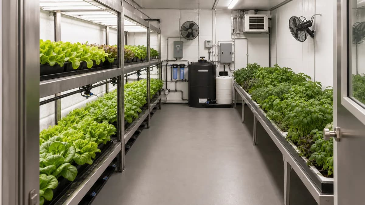
Plan a grow room by measuring the fixed boundaries first, reserving safe access, placing racks and service zones, mapping airflow through each canopy, and only then estimating plant capacity. The room must support plants, people, water, power, cooling, sanitation, and maintenance at the same time.
This guide gives you a repeatable way to do that. It does not certify a design for structural, fire, electrical, plumbing, accessibility, food-safety, or occupational compliance. Check the locally adopted rules and the authority having jurisdiction before construction. Use the rack and equipment manufacturers' instructions, and bring in a qualified professional where the design affects life safety, electrical work, HVAC, drainage, or structural loads.
Primary action: See the Garden Architect
Already planning a project? Open the setup after reviewing the public Garden Architect features. The setup route is a secondary action because it is an application surface rather than the public product page.
Table of contents
- Measure the room and fixed constraints
- Follow a room-first planning sequence
- Plan racks, aisles, and service clearance
- Place equipment and map airflow
- Estimate realistic plant capacity
- Hand off system choice and light coverage
- Sources
Measure the room and fixed constraints
An indoor grow-room plan should answer six connected questions:
- Does everything fit inside the measured room envelope? Record walls, ceiling height, doors, columns, windows, floor slopes, drains, pipes, ducts, beams, panels, and other fixed obstructions.
- Can people enter, work, turn, clean, and leave safely? Preserve applicable egress and accessible routes, then add the space needed for the operator, cart, harvest bin, tools, and mature foliage.
- Can every component be installed and serviced? A pump may fit against a wall but still be impossible to remove. A filter may need room for its housing to open. A rack may need access at both ends.
- Can water and electricity remain sensibly separated? Leak-prone equipment, wet work, and drainage need deliberate locations away from protected electrical working space.
- Can conditioned air reach each canopy? A room fan rating cannot show whether air moves across the leaves on a lower or middle tier.
- Can the room support the proposed crop load? Plant sites depend on mature spacing, light, irrigation, cooling, electrical supply, structural load, airflow, and labour access.
These questions form a series of gates. If a required route disappears when a door opens, the layout fails before crop capacity matters. If the service cover on an air-conditioning unit cannot open, the equipment zone needs to change. If the plants fit on paper but the cooling system cannot carry their moisture and heat loads, the plant count is not workable.
Start with three different area figures
Keep these figures separate from the beginning:
- Gross room area is the full floor area inside the room boundary.
- Net grow footprint is the floor occupied by usable racks, beds, trays, or systems after all exclusions.
- Total canopy area is the sum of usable growing surfaces across every tier.
A multi-tier rack can add canopy area without adding floor area, but the room's other capacities do not rise automatically. Each added tier brings more plants, lights, irrigation points, saturated operating weight, heat, humidity, and maintenance work. Research on multi-tier systems consistently treats tier geometry, air distribution, lighting, and non-growing equipment space as connected design constraints, not independent choices (Voutsinos et al., 2021; Sohn et al., 2023).
Draw constraints as objects, not notes
Put every exclusion on the plan at scale. Draw the door in its open position. Mark the electrical working zone as a rectangle that cannot hold racks or supplies. Show the full service envelope for tanks, filters, pumps, fans, dehumidifiers, air-conditioning equipment, and controls. Mark where a cart turns and where waste waits during cleaning.
Human-factors research by Guo and colleagues separates mere task possibility from a workable service posture. Their method includes the worker, tool, swept hand volume, reach, visibility, and body position. The study was not conducted in horticulture, so it does not provide a grow-room clearance. It does support a useful planning test: enough room for an object is not necessarily enough room to maintain it safely and repeatedly (Guo et al., 2018).
Use the plan to compare layouts, not certify them
A 3D model makes conflicts easier to see. It can help you compare rack orientation, door swings, equipment zones, and work routes before moving physical equipment. Keep the measured dimensions and manufacturer data beside the model. The plan still needs review against local rules, actual equipment, mature crops, and operating procedures.
See the Garden Architect to review the public planning features. Use it as a visual workspace for options, then verify every critical dimension outside the model before purchase or construction.
Follow a room-first planning sequence
Measure the fixed room first, reserve required access and equipment clearances, then place wet, electrical, airflow, storage, and work zones. Fit racks into the space that remains. Calculate plants from net canopy area and mature crop spacing, then test the plan for maintenance, leaks, airflow, power, drainage, and future expansion.
Step 1: survey the empty room
Measure width, length, and clear height at more than one point if the room is irregular. Record anything that reduces usable space, including an inward door swing, low beam, raised threshold, sloped floor, duct, panel, radiator, pipe, or existing drain. Mark the direction in which water moves across the floor.
Photograph each wall and fixed service. Give every obstruction a name that matches the drawing. This makes later checks easier when a proposed rack covers an outlet or a reservoir blocks a cleanout.
Record the equipment with the room survey. For each item, note:
- operating dimensions;
- door, lid, filter, or access-panel movement;
- inlet and outlet connections;
- hose, pipe, cable, or duct route;
- removal path for the largest service part;
- loaded weight and support requirements;
- manufacturer clearance and installation instructions.
Step 2: reserve protected clear space
Mark the routes and work zones controlled by the locally adopted building, fire, accessibility, electrical, and occupational rules. Do this before drawing cultivation equipment.
U.S. standards show why a generic aisle number is unreliable. The U.S. Access Board generally specifies a clear width of 915 mm (36 in) for an accessible walking surface in covered applications. Short reductions to 815 mm (32 in) are limited in length and arrangement. The 2024 International Building Code ties aisle and corridor width to occupancy and capacity; it includes a limited 711 mm (28 in) exception for certain nonpublic aisles serving fewer than 50 people that are not required to be accessible. These are different rules for different cases, and the adopted local requirements control (U.S. Access Board, 2010; International Code Council, 2024).
Electrical working space is another protected zone. For equipment covered by OSHA 29 CFR 1910.303 at 600 V or less, the working-space width is the equipment width or 762 mm (30 in), whichever is greater. Table S-1 gives clear depths of 0.9 to 1.2 m (3 to 4 ft), depending on voltage and conditions. The space must permit a 90-degree door opening and cannot become storage. These are U.S. general-industry examples, not worldwide defaults (OSHA 29 CFR 1910.303).
Step 3: map the work
Walk through a full crop cycle on the drawing. Include receiving inputs, filling tanks, transplanting, crop inspection, cleaning, harvesting, waste removal, and equipment service. Use the largest cart, bin, tool, or replacement part expected in each route.
Layout research supports this task-based view. Uyeh and colleagues modelled greenhouse paths around inter-bed space, turning, bed geometry, base location, and travel. Cross-aisles reduced return travel but consumed growing area. The model concerned robot navigation, not human life safety, yet it shows the trade-off clearly: a route can reduce nominal capacity while making repeated work more direct (Uyeh et al., 2019).
Step 4: place equipment zones
Place wet services, dry electrical and control equipment, air supply and return, work surfaces, sanitation supplies, storage, and waste holding before the racks. Draw connection paths and service zones as part of each object.
Avoid a single crowded equipment corner. Water may belong near containment and drainage, while controls need protection from likely spray and leaks. Air-conditioning equipment needs a service path and unobstructed air movement. Work surfaces need task lighting and a route that does not turn the main aisle into temporary storage.
Step 5: fit the racks and growing systems
Choose the growing method before you fix its footprint. Different systems change the position of reservoirs, return lines, drains, pumps, channels, and service points. Compare growing systems if that choice is still open.
Orient racks only after the air and work routes are visible. Check access to every tier and both ends of equipment that needs end service. Keep hoses and cables out of door swings and clear paths. If a movable rack is part of the proposal, draw it in every operating and service position.
Step 6: set tier pitch and plant spacing
Build tier height from the actual crop and hardware stack. Set plant spacing by cultivar, harvest stage, product form, light distribution, and growing method. Do not borrow one number from a study that used a different crop stage.
Light-fixture distance and distribution need their own calculation. Read the science of LED grow-light spectrum for the plant response behind fixture choices. The room plan should reserve the physical mounting and adjustment space without pretending that distance alone proves adequate light.
Step 7: test failure and change
Ask what happens if a hose disconnects, a drain slows, a pump needs replacement, a rack reaches full mature canopy, or a cart is left beside the workbench. Then test likely changes: a taller cultivar, a larger reservoir, another filter, a different light, or a future rack.
Keep at least one drawing that shows the room under mature and fully operating conditions. An empty-room plan hides the foliage, bins, hoses, tools, and service positions that often set the narrowest clearance.
Step 8: verify the installed room
Recheck dimensions during installation. After the room is operating, measure conditions at the canopy rather than assuming the drawing predicts them. Inspect multiple points and tiers for airspeed, temperature, and relative humidity. Confirm that routes and electrical working zones remain clear during ordinary work.
Planning CTA: Plan your room in 3D, then use the setup workspace as a secondary route when you are ready to build the scene.
Plan racks, aisles, and service clearance
Rack and aisle spacing should be derived from the widest binding requirement and the full vertical stack-up. Research facilities provide useful examples of how crops and hardware consume space, but they do not establish a universal safe aisle width or tier gap.
Calculate the clear aisle at its narrowest point
Use this planning rule:
planned clear aisle = maximum of egress requirement, accessibility requirement, operator and cart envelope, equipment service requirement, and local code requirement
The result is the clear width available during operation, not the distance between bare rack frames. Subtract mature leaves, fruit, hoses, handles, open lids, door swings, temporary bins, and any other predictable encroachment.
Li and colleagues described greenhouse crop rows that were 91.5 cm apart on the aisle side, with mature tomato leaves and fruit reducing the practical aisle to about 71.5 cm. Their robotic harvester had to be designed around that reduced width. The figures describe a specific greenhouse and machine; they are not human egress or accessibility standards (Li et al., 2024).
Jia and colleagues used a 500 mm operational aisle in a natural-light cultivation-frame study. That case shows that a narrow research installation can function for its stated experiment. It does not show that 500 mm complies with the rules or work needs of another room (Jia et al., 2024).
Compare those cases with the U.S. accessibility and model-code examples above. The values answer different questions. Never narrow a required accessible route, egress route, corridor, or electrical work zone to add plant sites.
Add cross-aisles and turning areas deliberately
A long uninterrupted aisle may save growing footprint while increasing travel and making carts harder to turn. A cross-aisle consumes floor space but can shorten repeated routes and provide another way to reach equipment. Uyeh and colleagues found this trade-off in their greenhouse navigation model (Uyeh et al., 2019).
Test the arrangement with the real work sequence:
- Can the largest cart pass a worker or reach a designated passing point?
- Can a harvest bin turn without entering another protected zone?
- Can a rack component leave the room without dismantling unrelated equipment?
- Does an open cabinet, reservoir lid, or filter housing block the route?
- Can staff reach a problem at the far end if part of the room is wet or closed for service?
Build rack tier pitch from the complete stack
Use this formula:
tier pitch = tray or channel depth + mature crop height + fixture depth + required crop-to-fixture distance + airflow gap + adjustment and service allowance
Measure each term from the equipment specification, crop plan, and service task. Crop-to-fixture distance must come from the selected fixture's output and target distribution, not a generic room-layout table.
Published lettuce systems show why one tier number does not transfer cleanly. Jia and colleagues used a 685 mm layer height in a natural-light, three-layer frame, with 350 mm between cultivation-trough units. Voutsinos and colleagues used a 1.9 m three-layer indoor rack; its high-light fixtures remained 400 mm above gully level, while the low-light fixtures moved from 200 to 400 mm during growth. Sohn and colleagues modelled 400 mm interlayer spacing in a container farm and considered a previously modelled 265 mm gap unrealistic for lettuce (Jia et al., 2024; Voutsinos et al., 2021; Sohn et al., 2023).
The three cases used different structures, lighting conditions, and research aims. They support the stack-up method, not a recommended range of 400 to 685 mm (Jia et al., 2024; Voutsinos et al., 2021; Sohn et al., 2023).
Check the rack as an operating load
Count the mass of the rack, trays or channels, saturated growing media, nutrient solution, lights, ducts, plants, tools, and any person who can load the structure during service. Use the rack manufacturer's rating and connection details. Shelf dimensions do not establish safe capacity.
The 2024 International Building Code calls for periodic special inspection of anchorage for certain steel storage racks at least 2.438 m (8 ft) high in Seismic Design Categories D, E, or F. It references ANSI/MH16.1 for anchorage installation. The Rack Manufacturers Institute lists ANSI MH16.1-2023 as the current industrial storage-rack standard. Whether either provision applies to a cultivation rack depends on the rack, use, adopted code, and project location (International Code Council, 2024; Rack Manufacturers Institute).
Do not estimate structural capacity from a 3D object. Confirm it with the manufacturer, local authority, and a qualified engineer where required.
Layout CTA: See the Garden Architect to compare rack and aisle arrangements visually. Keep code-controlled and manufacturer-required clearances in your measured plan.
Place equipment and map airflow
A good equipment layout separates incompatible work, preserves service access, and carries air, water, drainage, and power to the growing surfaces without crossing protected routes. Four zones provide a practical starting point: wet services, dry electrical and controls, air distribution, and work, sanitation, and storage.
Wet services
Group reservoirs, mixing, filters, pumps, drain-down points, and leak-prone connections where spills can be contained and removed. Leave room to remove lids, filters, pumps, and tanks. Draw both the operating position and the service position of each component.
Route hoses and pipes so they do not narrow an aisle, cross a door swing, or pass through protected electrical working space. OSHA requires dedicated space around covered indoor electrical installations to remain clear of foreign systems unless protection prevents damage from condensation, leaks, or breaks. That U.S. rule supports separation, but the local electrical design and equipment listings control the final installation (OSHA 29 CFR 1910.303).
Plan for drainage as an operating route. A floor drain in the room is not useful if racks prevent water from reaching it or stored supplies cover its service access. Keep wet cleanup from moving through the electrical zone.
Dry electrical and controls
Keep panels, drivers, controllers, communications equipment, and receptacles out of likely spray and leak paths. Preserve all required working and dedicated space. Do not use those zones for nutrients, tools, carts, or harvest bins.
Show cable routes and connection points on the drawing. Keep them away from water paths and places where routine cleaning, cart movement, or equipment doors can damage them. Electrical design and installation belong with a qualified professional under the rules adopted for the project.
Air supply, return, and local circulation
Draw a continuous supply-to-return path through every tier. Avoid placing a solid rack directly in front of a return or sending supply air straight back to the return without crossing the crop. Local circulation fans can help shelf-level movement, but total room flow still needs to carry heat and moisture.
Air changes per hour, usually shortened to ACH, describe bulk room flow. ACH does not prove that air reaches the canopy uniformly. Racks, lights, walls, and dense leaves change the local path.
The published evidence shows large configuration effects:
- Zhang, Kacira, and An tested four perforated-tube arrangements in a single-shelf lettuce system. Their preferred tested two-tube case averaged 0.42 m/s at the canopy with a 44% coefficient of variation (Zhang et al., 2016).
- Sohn and colleagues modelled one localized supply case averaging 0.65 m/s with a 33% coefficient of variation. A revised outlet layout reduced the coefficient of variation to 10%, showing how outlet placement changed uniformity in that container configuration (Sohn et al., 2023).
- Gao and colleagues modelled 20, 40, 60, 80, and 100 h⁻¹ across five crop-density resistance cases. More ACH often improved modelled temperature, humidity, and velocity uniformity, but the lowest-density case declined on the combined effectiveness measure at 100 h⁻¹ after peaking lower. Their result supports matching room flow with crop resistance and distribution geometry rather than choosing the highest available ACH (Gao et al., 2025).
- Zhang and Kacira compared five air-distribution designs in a commercial-scale model and found that localized delivery improved canopy climate uniformity. Multi-tier racks and heat from lights made uniform control harder (Zhang and Kacira, 2022).
These study speeds and ACH values belong to their tested or modelled systems. Do not use them as universal targets. Size the HVAC system from crop moisture and heat loads with qualified input. Commission the installed room by measuring airspeed, temperature, and relative humidity at multiple canopy points and tiers. Use a safe visualization method where appropriate to find short circuits and dead zones.
Work, sanitation, storage, and waste
Reserve a surface for transplanting, inspection, harvest, and cleaning. Give clean inputs, tools, bins, and waste assigned locations outside egress routes and electrical working space. If the operation requires separation between clean inputs, waste, and harvested produce, show those paths rather than relying on a written procedure that the floor plan makes difficult.
Make daily items easy to reach without hiding service panels. Store occasional items away from the central work route. The plan should still work on a busy harvest or cleaning day, when more bins and tools are present.
Reserve non-growing equipment space
Sohn and colleagues' shipping-container model left about 1.9 m of container length for controls, nutrient solution, carbon dioxide storage, and other equipment. That number is specific to their model and should not become a room percentage. It does provide a clear reminder that cultivation racks cannot occupy the whole enclosure (Sohn et al., 2023).
List every non-growing function before you estimate capacity:
- water storage and treatment;
- pumps, filters, and mixing;
- air-conditioning, dehumidification, and circulation;
- electrical and control equipment;
- transplanting, inspection, harvest, and cleaning;
- supplies, tools, carts, and bins;
- waste holding and removal;
- protected access and service zones.
Equipment CTA: See the Garden Architect to place equipment in 3D and compare zone arrangements. Use the setup workspace as a secondary action, then check the scene against physical dimensions and professional design requirements.
Estimate realistic plant capacity
Divide each net growing surface by the mature area needed per plant, then total all tiers. Keep aisles, service zones, equipment footprints, and egress out of the growing area. Reduce the result if light, airflow, irrigation, cooling, electrical supply, structural load, or labour access cannot support the calculated count.
Calculate net canopy area first
Use:
net canopy area = sum of usable growing surfaces after all exclusions
For a rectangular grid on one growing surface:
plants per zone = floor(zone length ÷ row spacing) × floor(zone width ÷ in-row spacing)
For a room with several crop zones:
estimated plant count = sum of plants calculated for each usable zone
Calculate each zone separately because rack lengths, edge exclusions, service gaps, and crop spacing may differ. Round down to complete rows and positions. Keep gross room area, net grow footprint, and total stacked canopy area visible beside the result so nobody mistakes one for another.
Define what kind of plant you are counting
Plant density is meaningful only when the crop, cultivar, harvest stage, and product form are named. A baby-leaf crop harvested young can use far more plants per square metre than mature heads. Higher density can raise harvested mass per area while reducing the size of each plant.
The research range looks contradictory until those differences are included:
- Jin and colleagues tested head lettuce at 23, 37, and 51 plants/m². Density changed intercepted light and the crop's response to far-red light (Jin et al., 2021).
- Maboko and Du Plooy found the highest winter yield among their tested soilless lettuce treatments at 50 plants/m², with results depending on cultivar and season (Maboko and Du Plooy, 2009).
- Barbosa and colleagues used an approximate 24 plants/m² greenhouse lettuce density in a resource comparison. Their model also tied high output per floor area to much higher energy demand than field production (Barbosa et al., 2015).
- Jadhav and colleagues grew baby-leaf lettuce and basil at 123, 237, and 680 plants/m² through 29 days after sowing. The highest density increased yield per area and light-energy-use efficiency but reduced fresh and dry mass per plant, with different responses by species (Jadhav et al., 2025).
- Saito and Goto assessed young komatsuna at 250 plants/m² at 18 days after sowing. Their work also describes how excessive density can reduce light per plant and affect morphology and lower-leaf condition (Saito and Goto, 2023).
Do not average these densities. The baby-leaf and young-plant figures cannot be used as mature-head capacity. Select spacing from a current source for the crop, cultivar, harvest stage, and production method you intend to use.
Apply the capacity caps
The arithmetic gives a first estimate. The supported capacity is the lowest limit imposed by:
- usable growing surfaces;
- crop spacing and mature canopy size;
- measured light intensity and uniformity;
- irrigation delivery and drainage;
- cooling, dehumidification, and canopy airflow;
- available electrical supply;
- rack, floor, and anchorage capacity;
- access for crop work and equipment service;
- sanitation and waste handling.
If one tier receives poor light or develops a stagnant canopy zone, its theoretical plant sites do not count as supported capacity. If adding another tier blocks fixture adjustment or filter removal, the tier does not fit operationally. If a saturated rack exceeds a rated load, reducing plant count alone may not resolve the structural problem.
Voutsinos and colleagues' lettuce rack held 30 plants/m² and used fans at both rack ends, while the light treatments differed in distance and crop result. Jin and colleagues showed that density changed light interception, and Gao and colleagues modelled an interaction between crop resistance and ACH. Together, the studies show why plant count, light distribution, and airflow cannot be finalized as separate spreadsheets (Voutsinos et al., 2021; Jin et al., 2021; Gao et al., 2025).
Compare scenarios instead of chasing one maximum
Prepare at least three versions:
- Conservative layout: fewer growing surfaces, generous service access, and room for change.
- Working layout: the expected crop mix, equipment, and daily workflow.
- High-density layout: the highest count you want to test, with every added demand on light, irrigation, cooling, power, structure, and labour listed beside it.
The comparison makes trade-offs visible. A cross-aisle may remove plant sites but shorten work routes. A larger wet zone may lower nominal capacity but make filter changes and spill response practical. A lower tier count may permit taller crops, better fixture adjustment, or a clearer air path.
Use the working layout as the baseline until measured operation supports a denser version. Record the crop stage and spacing assumption beside every plant-count result.
Capacity CTA: See the Garden Architect to test plant-spacing scenarios visually. The planner helps compare arrangements; it does not supply crop spacing, validate plant capacity, or certify the room.
Before committing to the layout, make one final pass in this order:
- Confirm the measured room and every fixed obstruction.
- Confirm local egress, accessibility, electrical, fire, plumbing, and occupational requirements.
- Confirm equipment dimensions, service positions, connection routes, and manufacturer clearances.
- Confirm the rack and floor design against saturated operating loads.
- Confirm that wet services and protected electrical space do not conflict.
- Confirm an air path through each tier and a plan for canopy-level commissioning.
- Confirm crop spacing by cultivar, maturity, and harvest form.
- Confirm that all routes remain clear with mature plants and ordinary work items present.
Hand off system choice and light coverage
This guide owns the room plan, not the choice of hydroponic method or the calculation of fixture coverage. If the growing method is still open, use the hydroponic system planning guide to compare crop fit, footprint, power, water, and maintenance at a decision level.
Once the racks and canopy areas are placed, use the grow light placement and coverage guide to work through fixture spacing, mounting height, overlap, and canopy-level PPFD maps. Spectrum and plant responses to light quality remain in the LED grow light spectrum guide.
See the Garden Architect to compare room arrangements. Treat the product as a visual planning workspace, then verify system requirements and light coverage with their canonical guides.
Last verified:
Put the guide into practice
Use Truleaf Garden Architect to map the space, equipment, and growing system before you build.